Sinus-Cosine Modulator – The Ideal Power Amplifier
Designing a power amplifier for audio applications remains one of the most challenging technical tasks even today. Until now, even the best analog power amplifiers have had their own "sound," based on a classic issue in amplifier technology: the stability criterion of feedback. Analog amplifiers (voltage-controlled voltage sources) consist of multiple amplifier stages, each of which, whether built with transistors or tubes, operates non-linearly (exponentially) by design. Linearization requires feedback, which feeds a portion of the output voltage back out of phase to the input (or in-phase to a second, inverting input). The higher the number of amplifier stages covered by feedback, the stronger the linearization. However, because there are no amplifier stages that are "infinitely fast," the feedback arrives "too late." At higher frequencies, a phase shift occurs, making the feedback unstable and eventually positive. To prevent the analog amplifier from oscillating, frequency compensation is required, reducing the open-loop gain (total gain without feedback) and, with it, the linearization at higher frequencies. Every analog power amplifier sounds different because the "large" power transistors in the output stage are not fast enough or cannot be driven fast enough, and the overall feedback cannot retroactively reduce all nonlinearities to an inaudible level.
Since the 1970s, almost every circuit variant has been tried to improve the sound quality of analog power amplifiers (Class A or AB). We won't delve further into this here, as the effort is disproportionate to the benefit. Since the 1990s, pulse-width modulation amplifiers (Class D) have been available, which generate no inherent heat losses and now achieve a level of sound quality that traditional analog power amplifiers can no longer match. That the latter have not yet become obsolete is mainly because the inherent superiority of PWM amplifiers is not so easy to implement in practice, and the necessary know-how is still not available to all manufacturers.
PWM Amplifiers
A PWM (Pulse Width Modulation) power amplifier does not become unstable, as it is already an oscillator! The open-loop gain can be set "infinitely high," and the output stage transistors no longer need to "burn" any power, they only need to do one thing: switch very quickly! The quality of signal processing, or the sound quality, then depends on how precisely the switching points can be controlled over time. In the following example, this task is performed by an ultra-fast, symmetrical precision comparator, the LT1713:
What an analog push-pull power output stage, even in Class A operation (i.e., with maximum heat loss), cannot do, works with a PWM amplifier (almost) without heat loss: With optimal dimensioning, the power switching stage already works in open-loop mode, i.e., without feedback, as a linear power amplifier with no audible distortion! However, the simulation involves idealizations that are not easy to implement in practice:
- The MOSFET drivers are ideal voltage-controlled voltage sources with galvanic isolation.
- The triangular signal determining the switching frequency, d1, is an ideal triangle.
- The power supply has a minimum internal resistance of only 1 mΩ.
If the galvanic isolation between the pulse-width modulator and the power switching stage is omitted, which "only" requires a very good PCB layout, a modern half-bridge MOSFET driver such as the LM5100 comes very close to the ideal. Whether the propagation delay is zero or 25 ns makes little difference as long as the delay times from one switching period to the next and for the positive and negative half-wave are identical.
Generating a clean triangular signal, especially at a frequency of 400 kHz, is one of the more challenging circuit design tasks, as any electronics engineer who has attempted this will confirm. Any deviation from the ideal triangle leads directly to non-linear distortions, making this point decisive for the sound quality of a PWM amplifier.
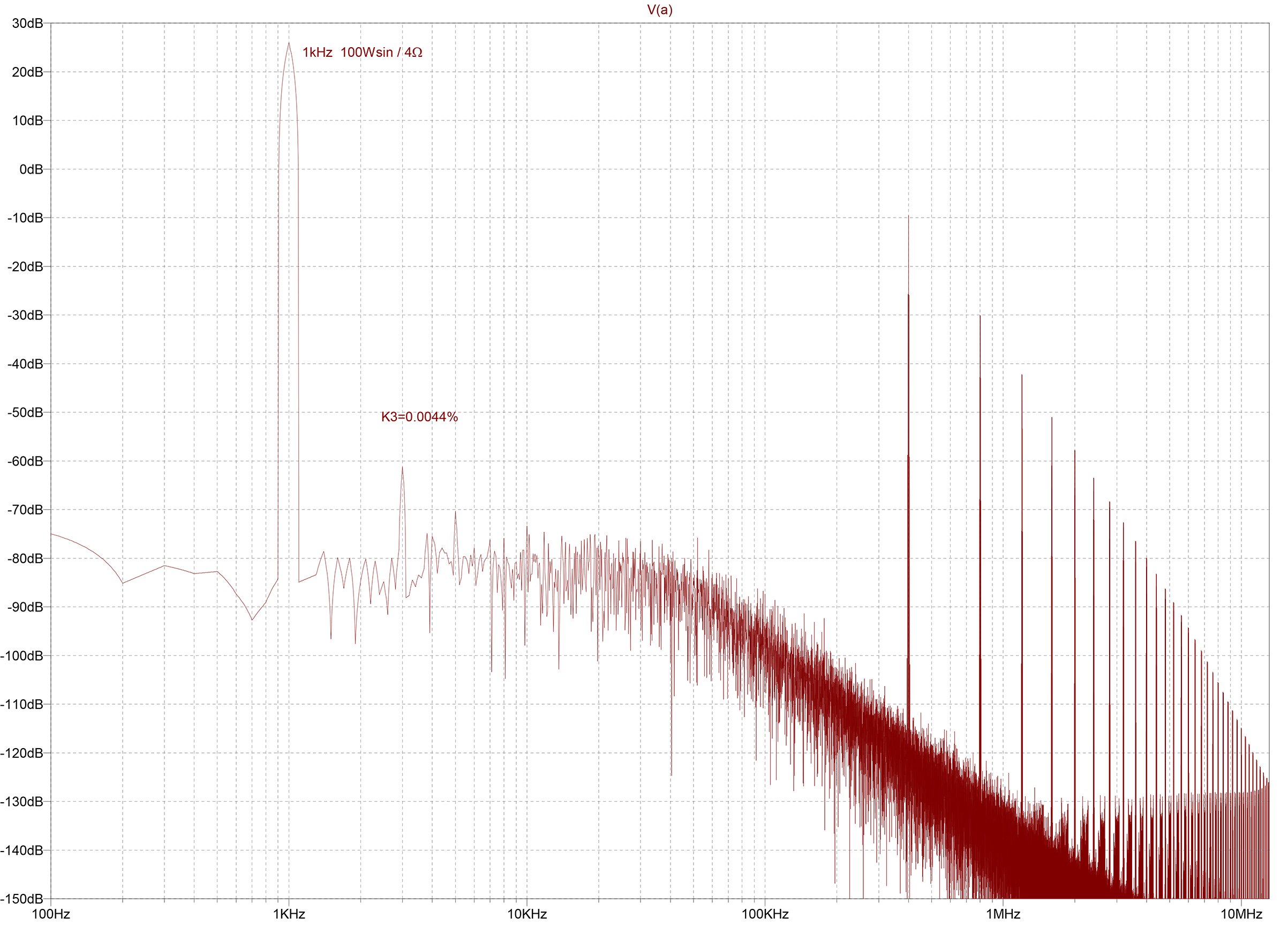
A power supply with only 1 mΩ internal resistance is hardly achievable in practice. The weakness of the open-loop design, with a PSRR (Power Supply Rejection Ratio) of zero, becomes evident when the internal resistance increases to, for example, 300 mΩ:
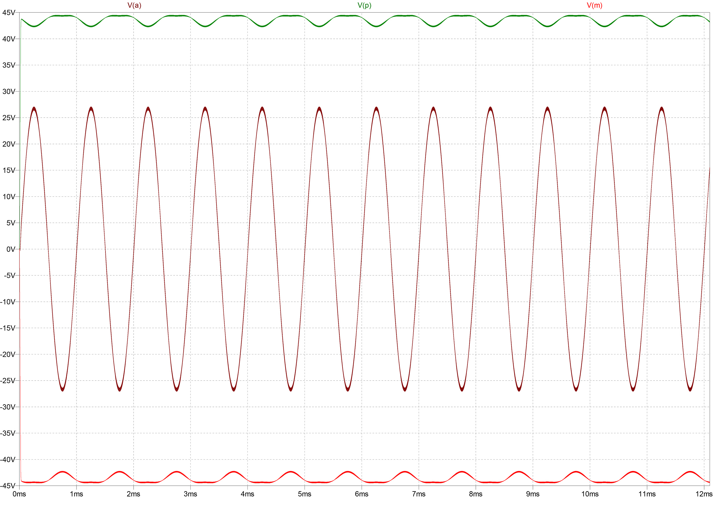
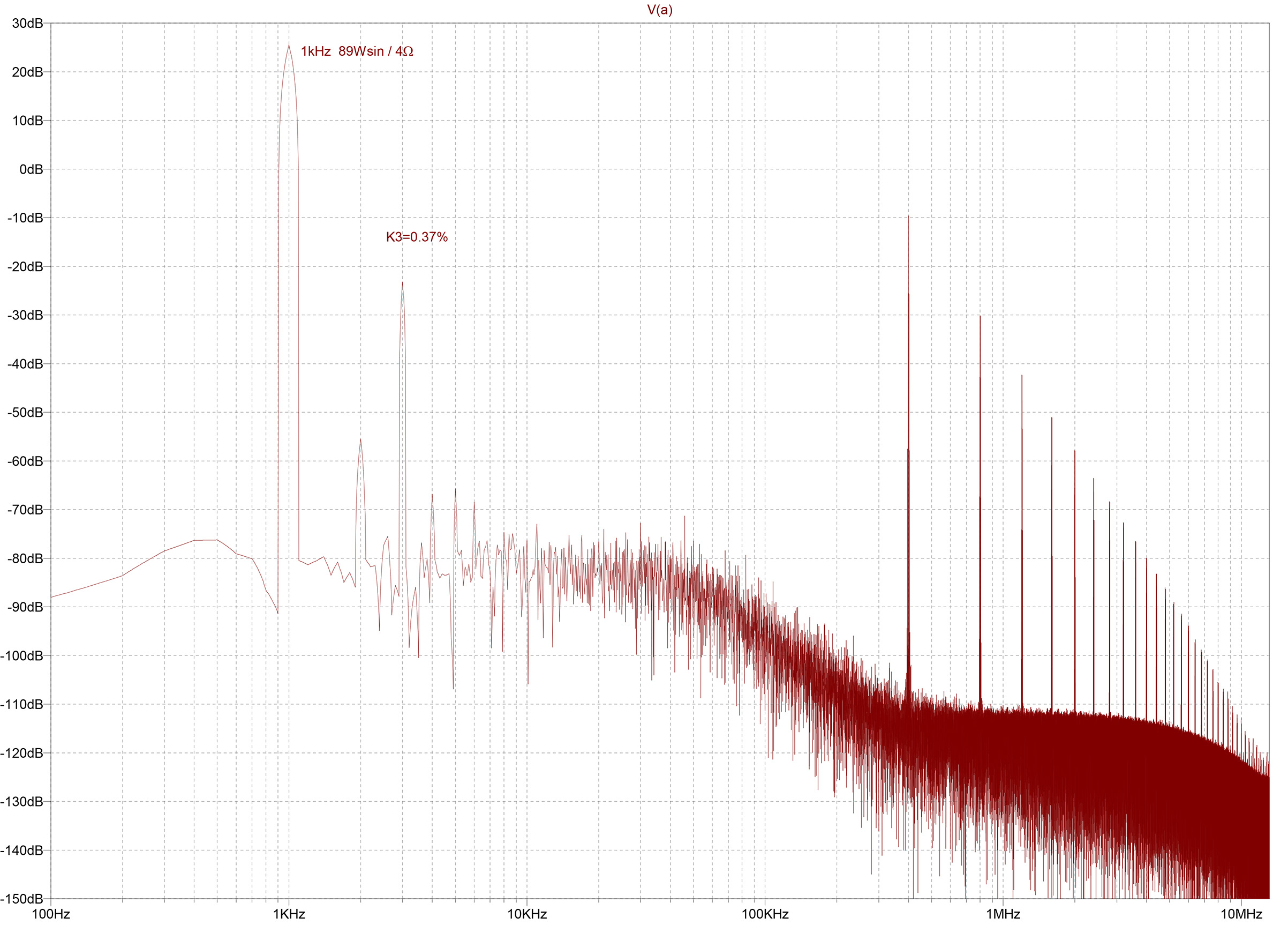
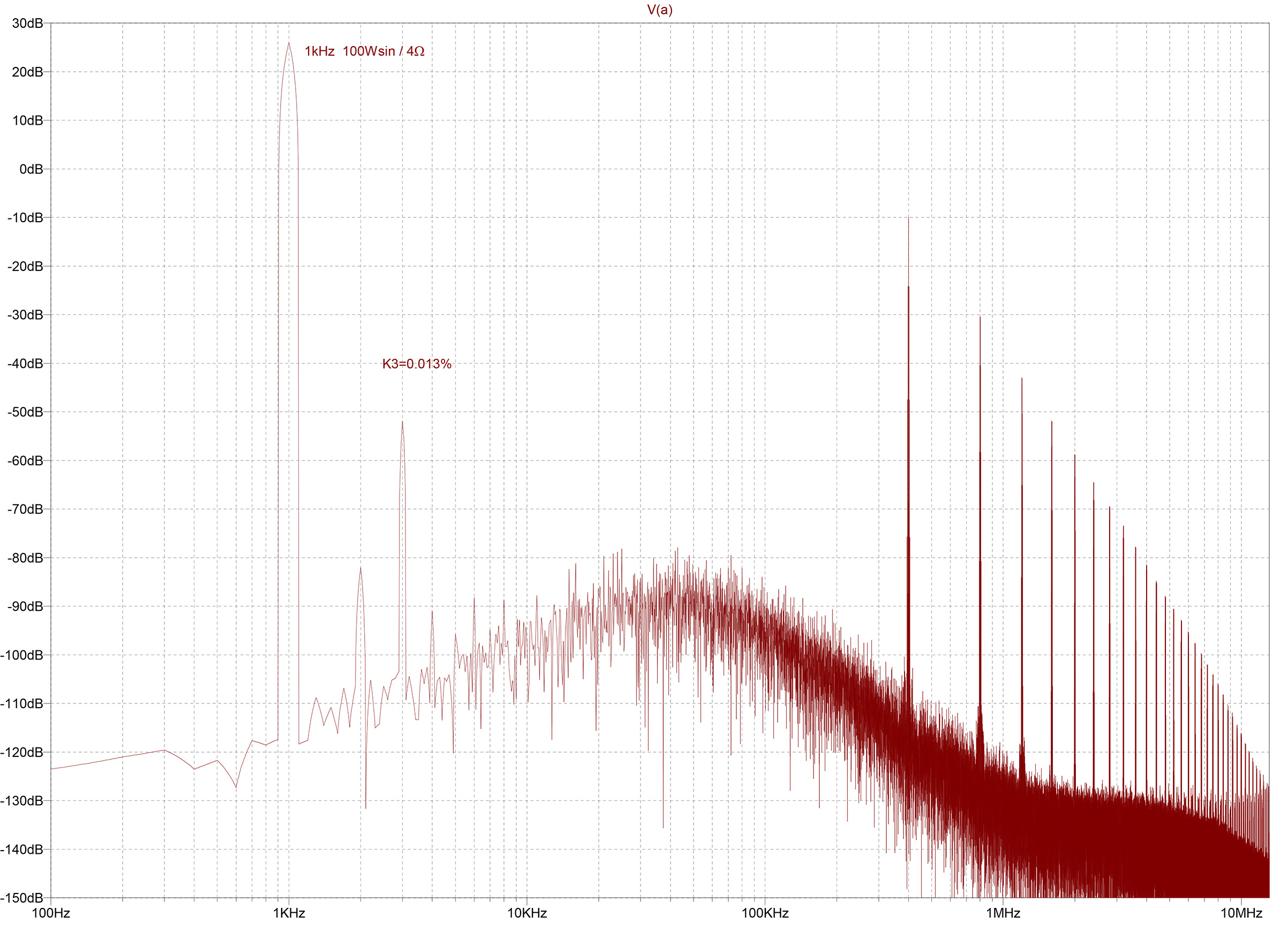
The 1 kHz sine output voltage V(a) is distorted with every drop in the supply voltages V(p) and V(m) (Vs drops from 28.3 V to 26.7 V), reducing the output power at the same input voltage to about 89 Wsin and causing an audible third harmonic distortion of 0.37%. Therefore, feedback is required, but unlike with analog amplifiers, it only needs to increase the PSRR rather than correct the nonlinearities of the output transistors. An inverting integrator with a fast and low-noise operational amplifier (LT1818) is placed before the comparator input, resulting in a closed-loop PWM amplifier with a gain factor A = -(R6+R9)/R7 = -22.5, independent of the supply voltage:
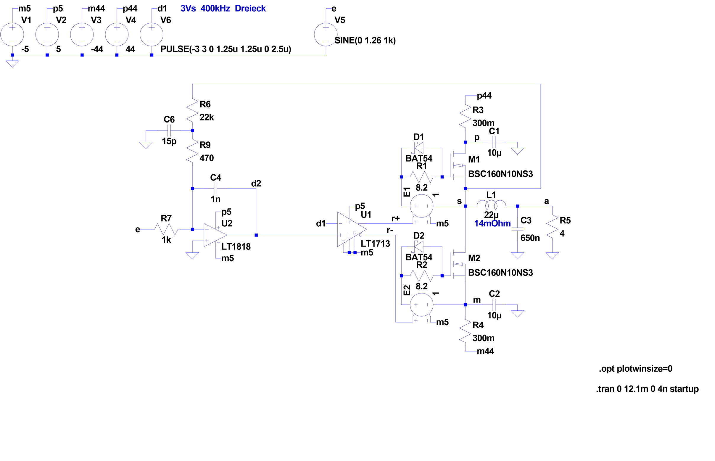
In theory, we now have a very good linear amplifier that, unlike classic analog power amplifiers, does not produce zero-crossing distortions and therefore sounds completely "effortless." However, this only applies if the triangular signal determining the switching frequency, d1, is an ideal triangle. The external triangle generator is not included in the feedback loop, so in practice, any deviation from the ideal triangle increases the distortion level. It is better if the PWM amplifier oscillates on its own. There are various ways to achieve this.
The UcD Principle
The so-called Universal Class-D amplifiers are based on a patent by Philips. What stands out in the application circuits is the slow and imprecise comparator built with standard transistors and the even slower MOSFET drivers, which resemble hobbyist circuits rather than modern circuit design:
Why aren't modern integrated half-bridge MOSFET drivers and fast precision comparators used here? Is it because the "hobbyist gear" is so nice and cheap? No. The UcD principle cannot handle the minimal switching delay times of under 25 ns (LM5100) or even under 10 ns (LT1713) and instead relies on the slowness of the components! Because no provision is made to set the switching frequency of a self-oscillating UcD amplifier independently of all other parameters, the circuit oscillates too quickly when built with high-quality electronic components:
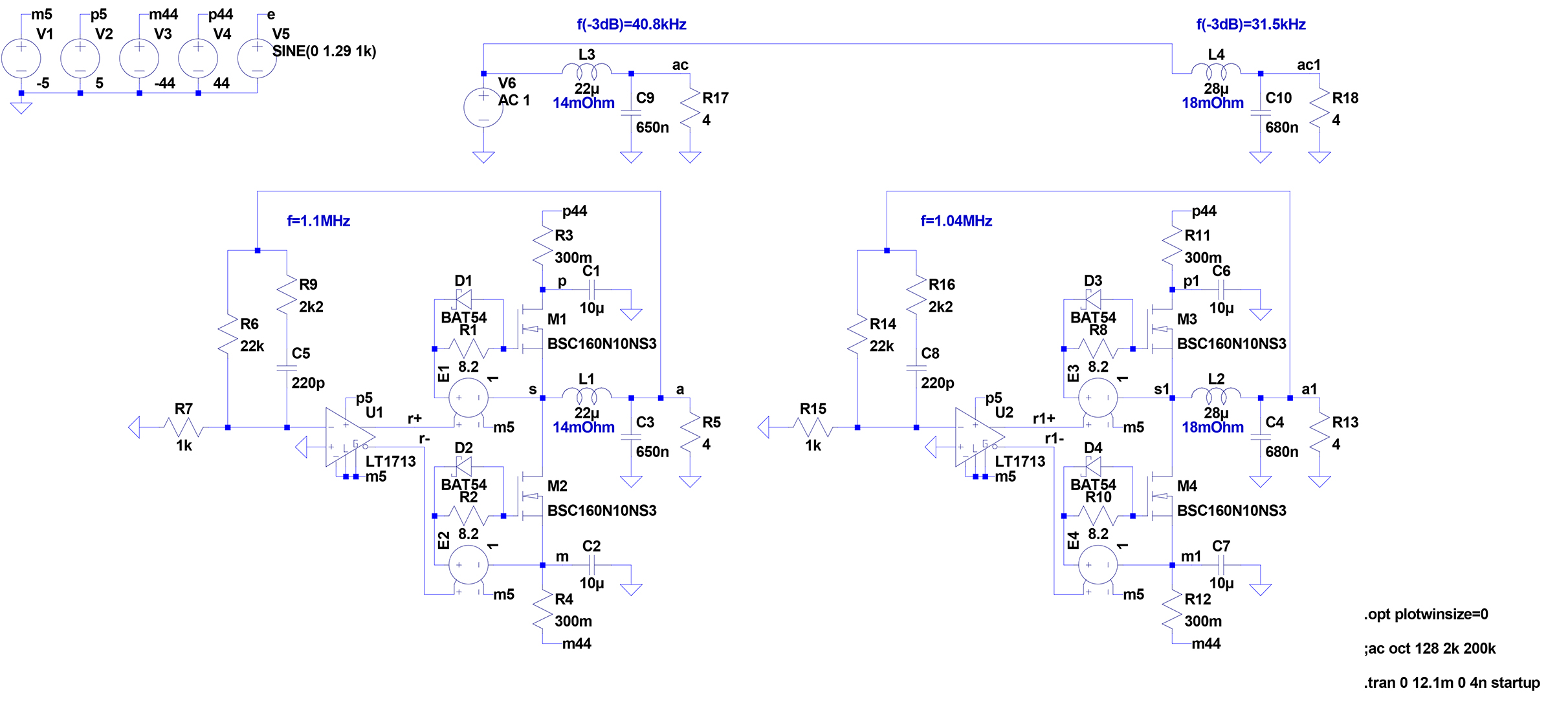
The two UcD amplifiers differ only in the design of their respective LC output filters, which are included in the feedback loop. The switching frequency, controlled by the ripple voltage of the output stage behind the LC output filter, is too high at 1.1 MHz and 1.04 MHz. What works in the simulation results in excessive switching losses in practice. One way to reduce the switching frequency would be to add hysteresis to the comparator, but this would drastically increase nonlinear distortions. In reality, there is no other choice but to use a slow and imprecise comparator built with standard transistors:

The still relatively low distortion level is sufficient for the upper mid-range, but unfortunately, UcD is not truly a linear amplifier. For it to be, the voltage gain A = -R8/R10 = -22 would have to be independent of the input signal frequency. However, R12-C4 is connected in parallel with R8, so that A is reduced to -20.8 at f=1kHz and to -19.4 at f=10kHz. As a result, the actual 100 Wsin into 4Ω becomes only 89 Wsin, or just 78 Wsin. The FFT analysis also shows that the switching frequency is not constant but "smears" over a certain range. All parameters in the circuit are interdependent in unpredictable ways. In practice, a UcD cannot be designed but can only be "tweaked" to work. The sonic outcome is more or less a matter of luck. The only advantage is that the LC output filter, included in the feedback loop, does not need to be matched to the respective load impedance, making UcD "universal" for driving any passive multi-way speaker system with unknown and fluctuating load impedance. This advantage is irrelevant for high-quality full-active systems. Therefore, the UcD principle is not the ultimate solution.
The Hysteresis Converter
If the "universality" of the LC output filter is abandoned, feedback can again be applied directly at the output of the power switching stage. To obtain a self-oscillating PWM amplifier that compensates for all internal nonlinearities as well as fluctuations in the supply voltage through feedback, the comparator simply needs to be extended with two additional resistors, turning it into a Schmitt trigger with two defined switching points:
The SODFA Principle
A variant of the hysteresis converter is the Self Oscillating Digital Feedback Amplifier (according to patent application DE 198 38 765 A1), where the entire power switching stage forms a coupled Schmitt trigger, with the switching points proportional to the supply voltage:
When constructed correctly with the best electronic components available today, the hysteresis converter and SODFA outperform the sound quality of any classic analog power amplifier in listening tests! The FFT analyses shown here can only provide some guidance. If the simulated and measured static distortion factors remain below 0.01%, other factors determine how the amplifier actually sounds in practice. Various sophisticated measurement methods can be devised to "objectively" assess the behavior of power amplifiers with non-static or non-periodic signals. However, all these methods provide only further clues and cannot yet fully explain why one amplifier "sounds" and another does not.
At this point, it is clear that PWM amplifiers sound better than classic analog power amplifiers because, when optimally dimensioned, the power switching stage already operates linearly without feedback. As already mentioned, the high sound quality is achieved through the fast precision comparator. With a gain-bandwidth product of over 50 gigahertz, an LT1713 can set the switching points of the power switching stage much more precisely than the pre-driver stages of a classic analog power amplifier can control the relatively slow output transistors burdened with large heat losses to always follow the audio input signal.
Self-oscillating PWM amplifiers, in turn, sound better than those clocked by a separate triangle generator. An exception to this rule is the UcD, which works only (somewhat) with a slow and imprecise comparator. The disadvantage of the clocked CL-PWM amplifier is that, while its feedback loop compensates very well for load and supply voltage fluctuations, it does not compensate for the errors or nonlinearities of the controlling triangle generator. In contrast, an SODFA is a self-coupled power square-triangle generator that regulates all internal nonlinearities with maximum efficiency.
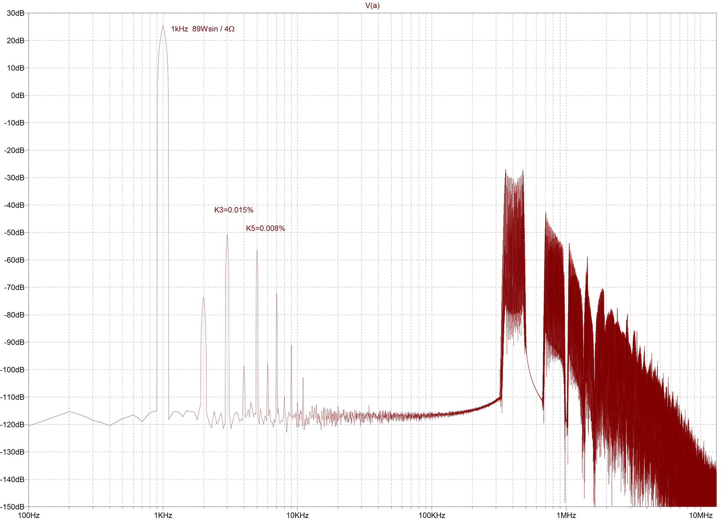
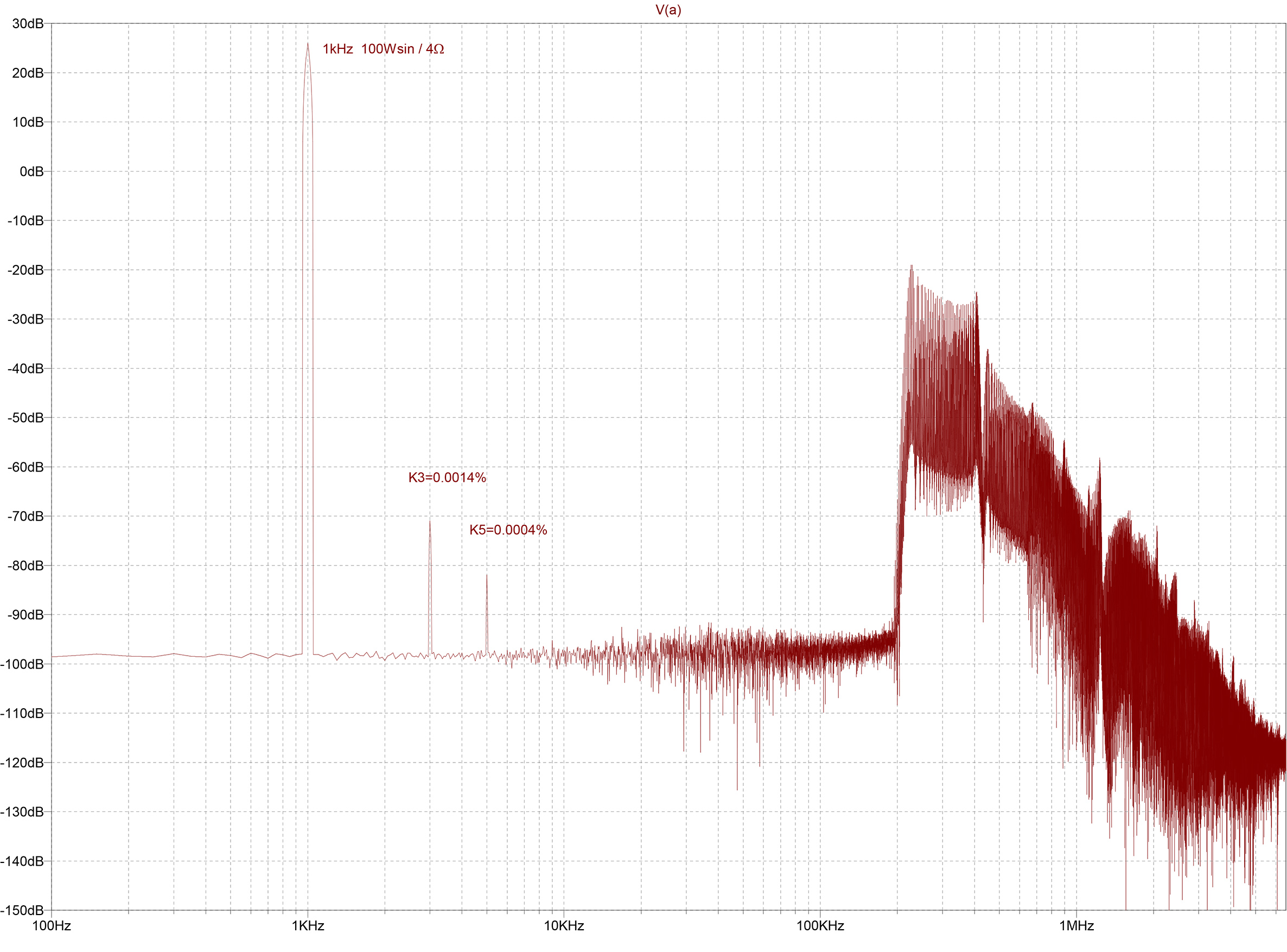
However, like the UcD, the hysteresis converter and SODFA still have an undesirable dependence of the switching frequency f on the modulation index M, which for the SODFA can be calculated as f=f0*(1-M2). Already at half the maximum output voltage (corresponding to a quarter of the maximum output power), the switching frequency drops to 75% and approaches zero near the clipping limit. Therefore, if the switching frequency of a self-oscillating PWM amplifier can be made independent of the modulation index, the goal will be reached: the ideal power amplifier.
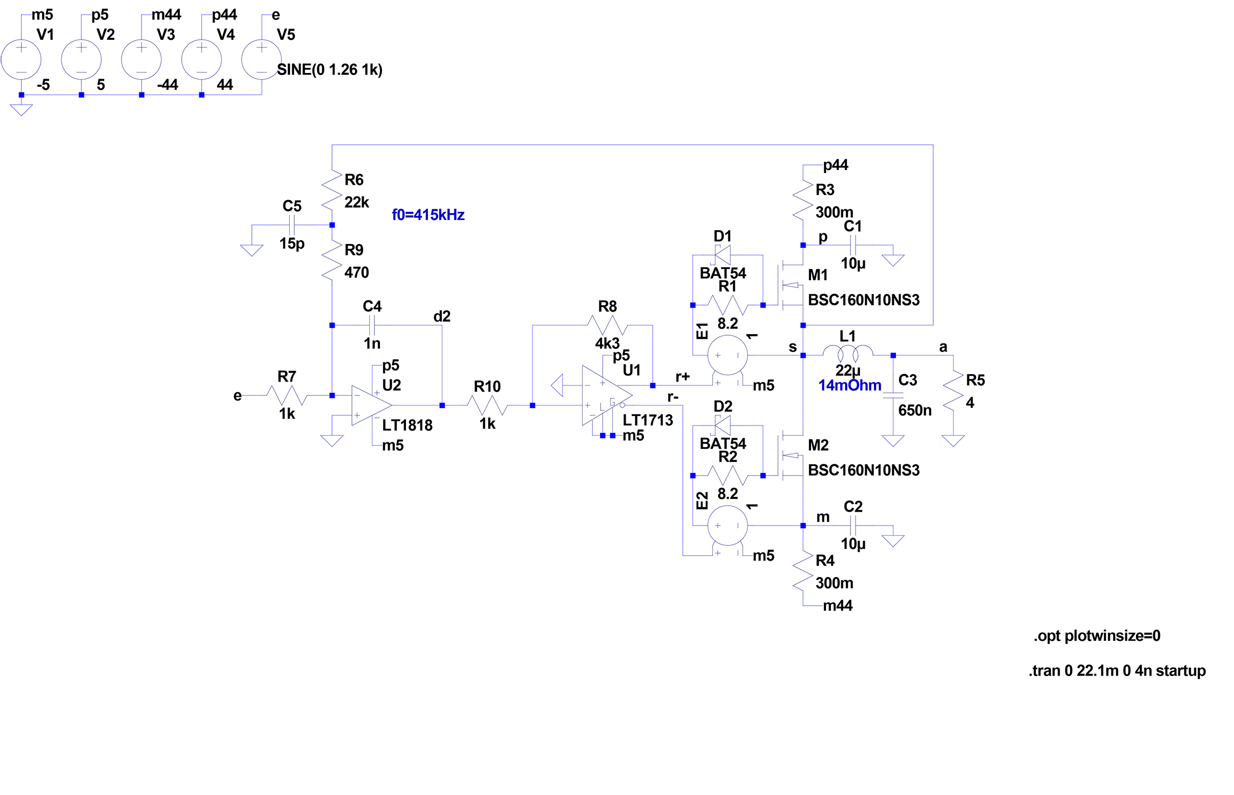
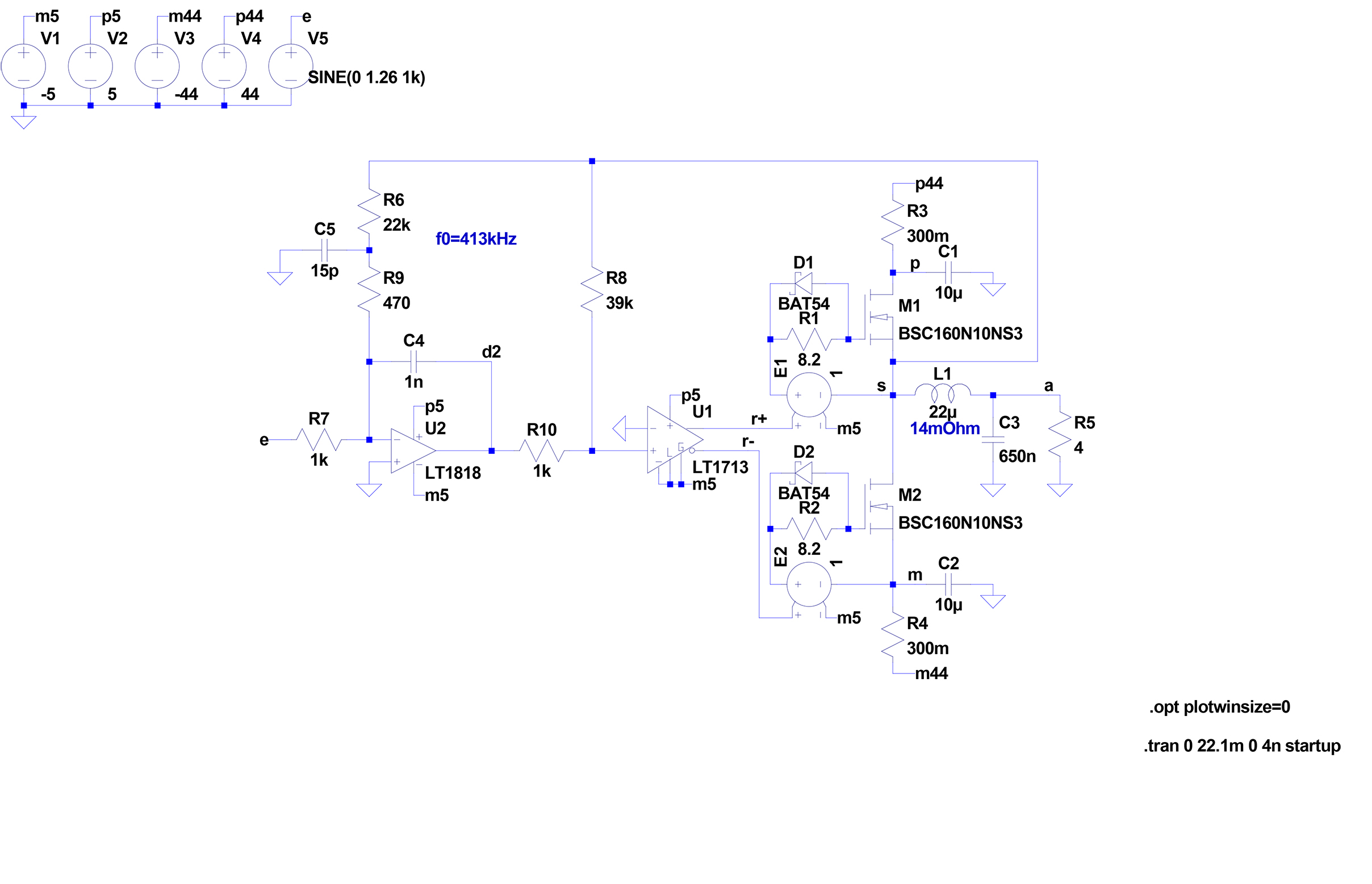
The Sinus-Cosine Modulator
Strictly speaking, the ideal linear amplifier remains a theoretical ideal that cannot be fully achieved in practice but can only be continuously approached. The ideal audio power amplifier only needs to be better than the human ear. Whether this has already been achieved with the Sinus-Cosine Modulator (US-Pat. 9,287,826) is hard to assess, but no better amplifier has been found so far. An SODFA can drive a speaker more precisely than a clocked PWM amplifier and much more precisely than classic analog power amplifiers. It can be shown that a Sinus-Cosine Modulator sounds even slightly more open, dynamic, and controlled than an SODFA. Beyond that, there is no comparison.
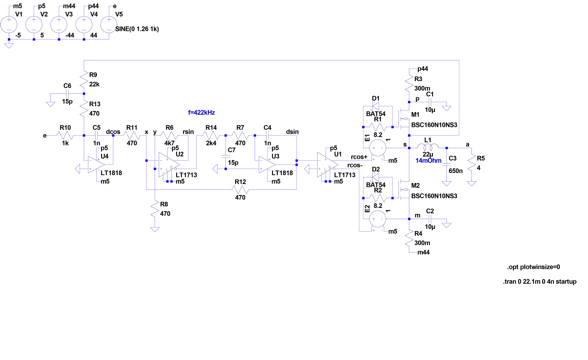
The trick is to integrate a highly precise "inner" square-triangle generator into the feedback loop of an "outer" power square-triangle generator. The "inner" square-triangle generator keeps the switching frequency constant, while the audio-input-signal pulse-width-modulated "outer" square-triangle generator controls the power switching stage. This creates an extremely stable second-order control loop, in which the two triangle signals and the two square signals are each phase-shifted by 90° relative to each other. Hence the name Sinus-Cosine Modulator:
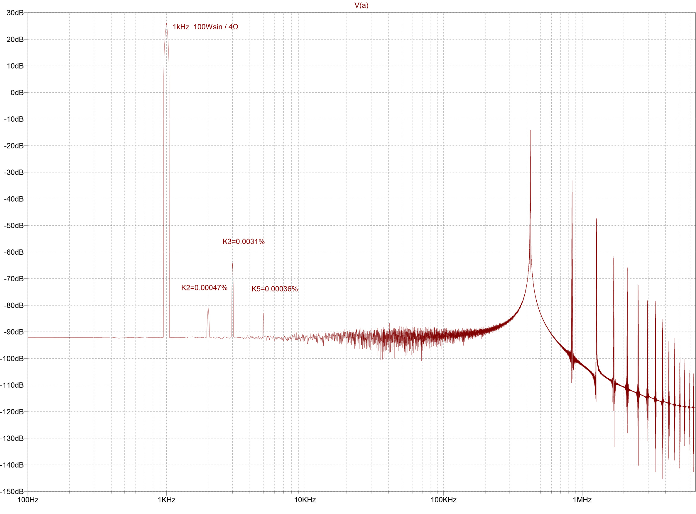
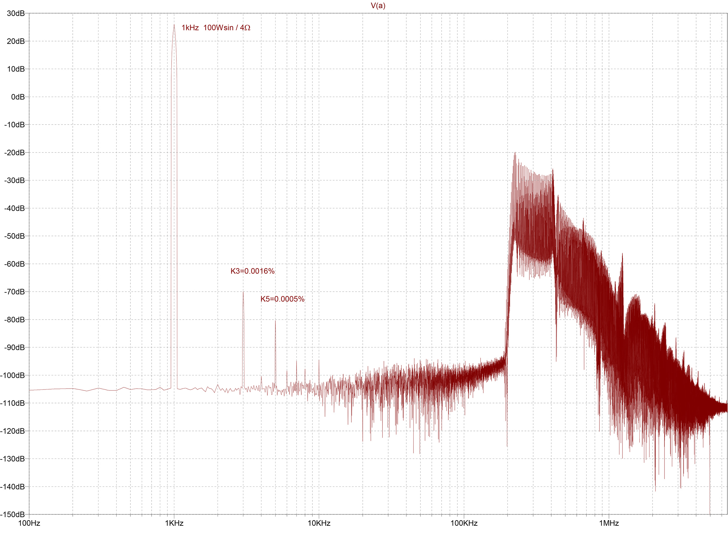
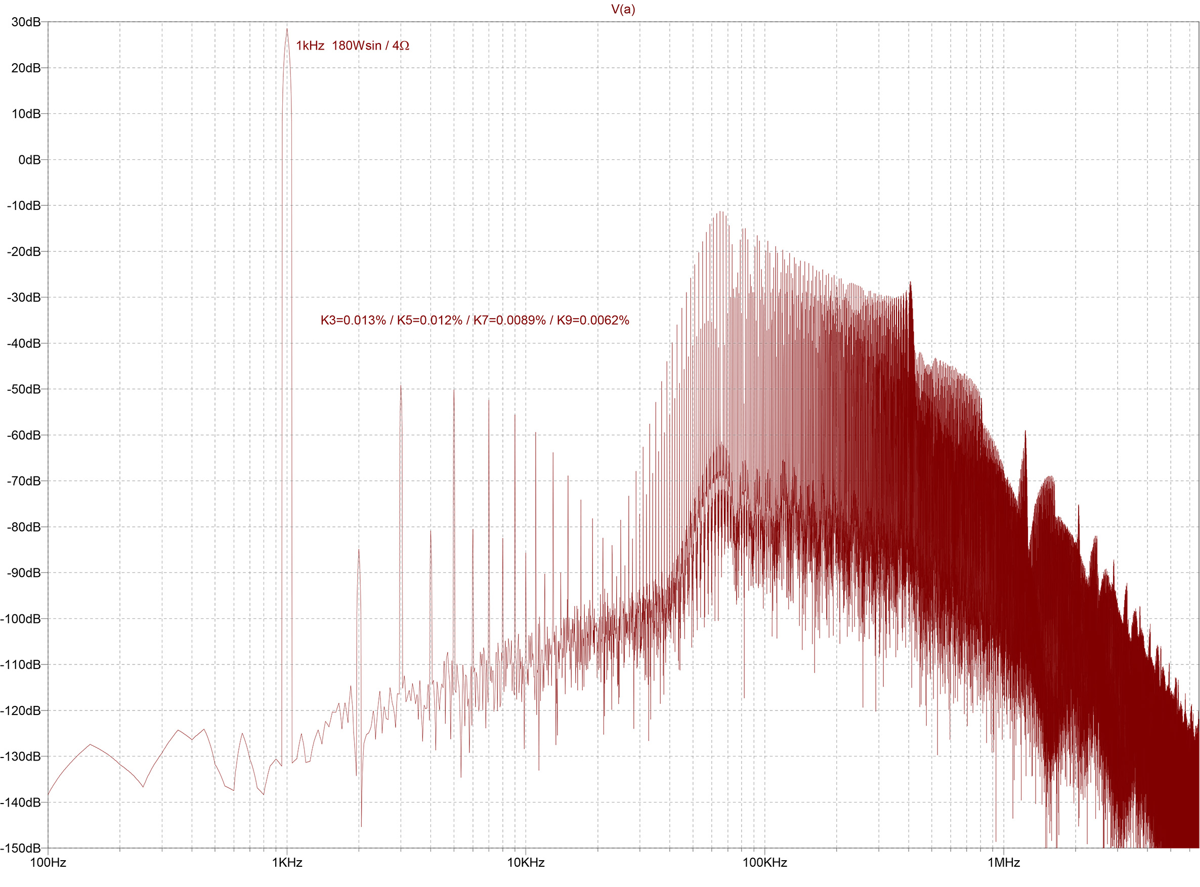
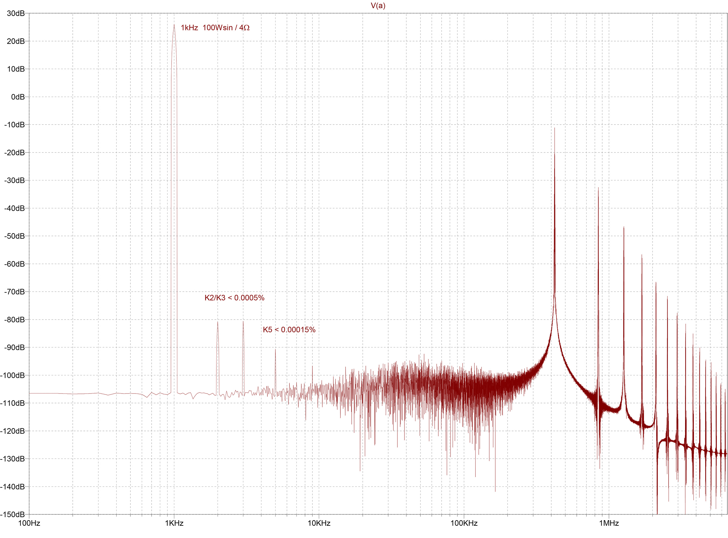
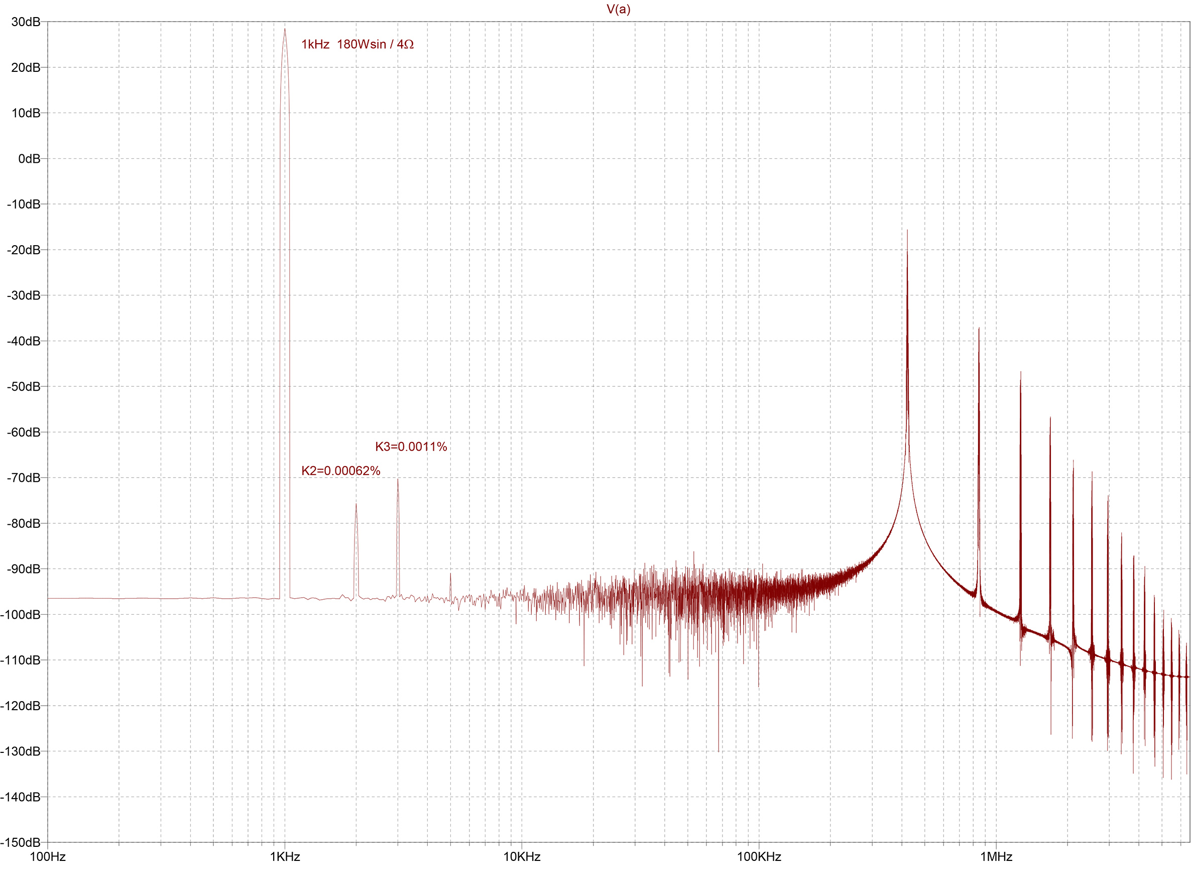
The FFT analysis again can only provide a clue; ultimately, the listening test is decisive. From a measurement perspective, the superiority of the Sinus-Cosine Modulator over the SODFA becomes especially apparent at maximum sine wave output power:
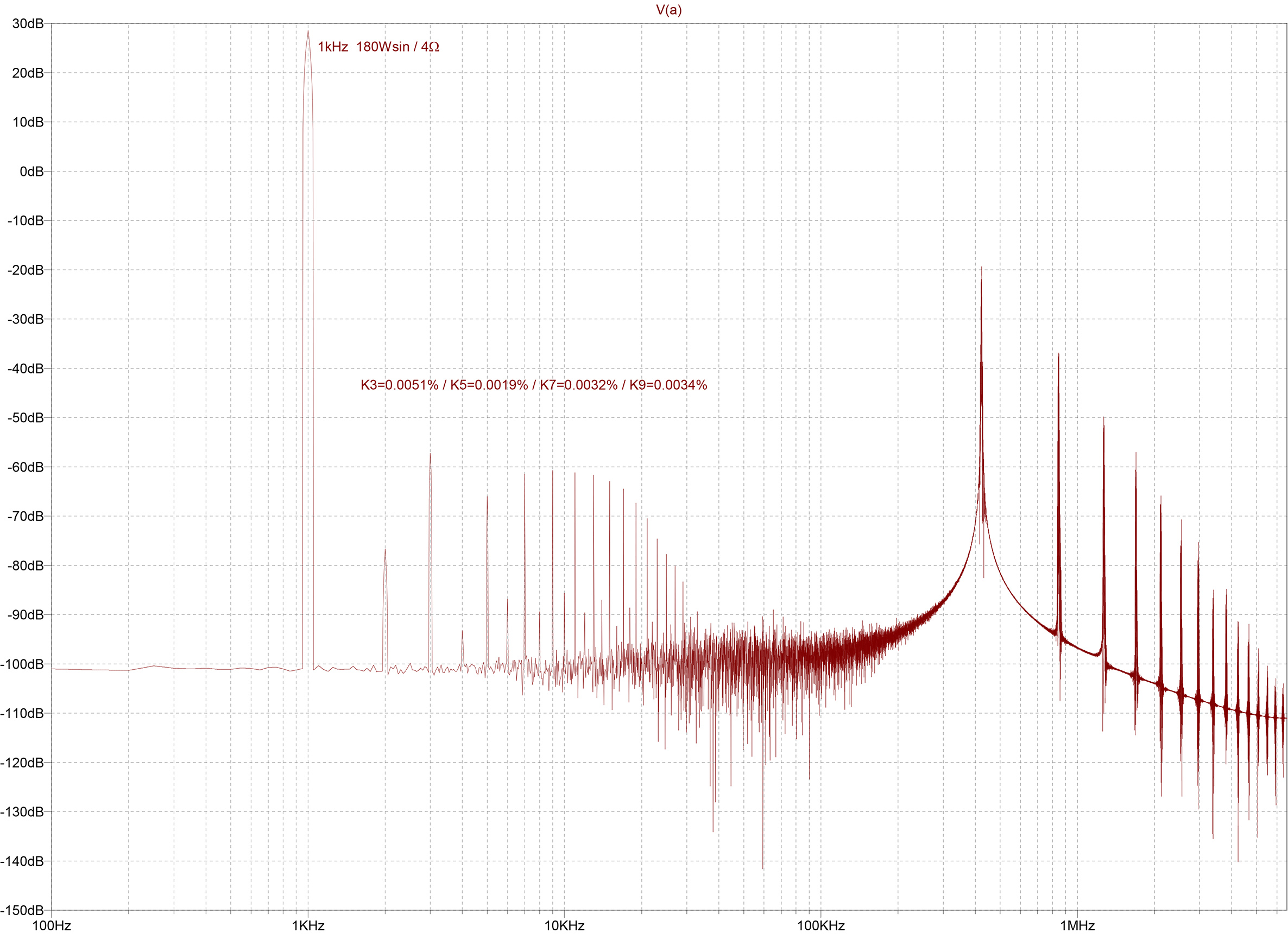
To improve sound quality to the limit of what is technically feasible, the SINCOS® power output stages are designed as symmetrical full bridges:
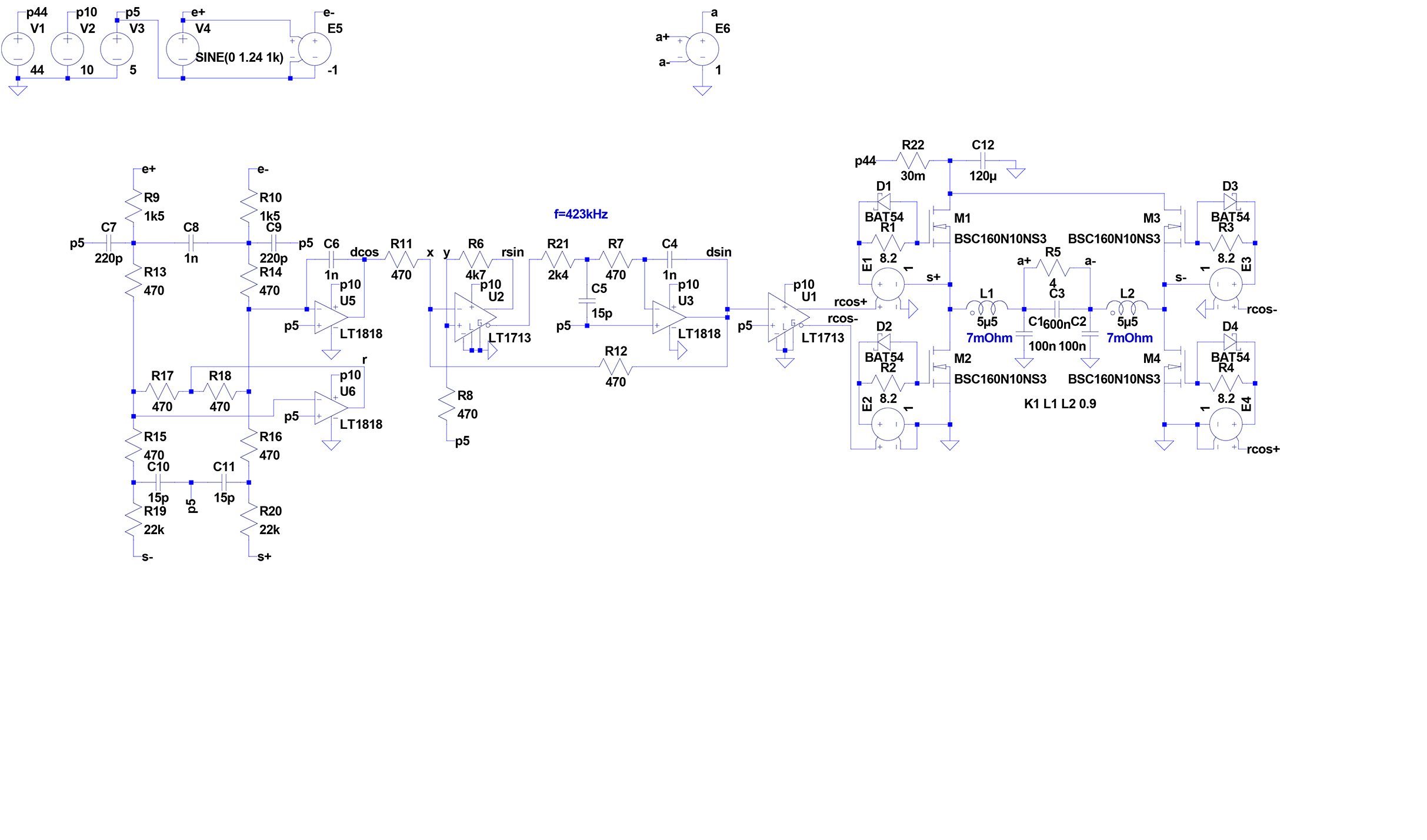
Among other advantages (symmetrical signal input, improved linearity, no "bus-pumping," reduced RF on the speaker cables), a full-bridge circuit allows the output inductor to be optimized, which is subject to high demands. An air-core coil has too high DC resistance and would also need elaborate shielding. A coil with an iron powder core, where the "air gap" is distributed over the entire magnetic path length, has higher remagnetization losses at 400 kHz than a ferrite core coil with a slotted air gap. However, the latter generates a magnetic stray field that induces non-linear distortions in the copper windings above. In a full bridge, two identical inductors are magnetized in counter-phase. If both inductors are symmetrically wound on a common HF ferrite core, with the air gap exactly in the middle between the copper coils, the induced non-linear distortions cancel each other out. The copper coils consist neither of a single thick wire nor of HF litz wire (many very thin wires), but of four parallel enamelled copper wires of medium thickness, so that there is no significant skin effect at 400 kHz, and at the same time, the higher frequency harmonics are better dampened. Such construction details are more important with PWM amplifiers than many other things.
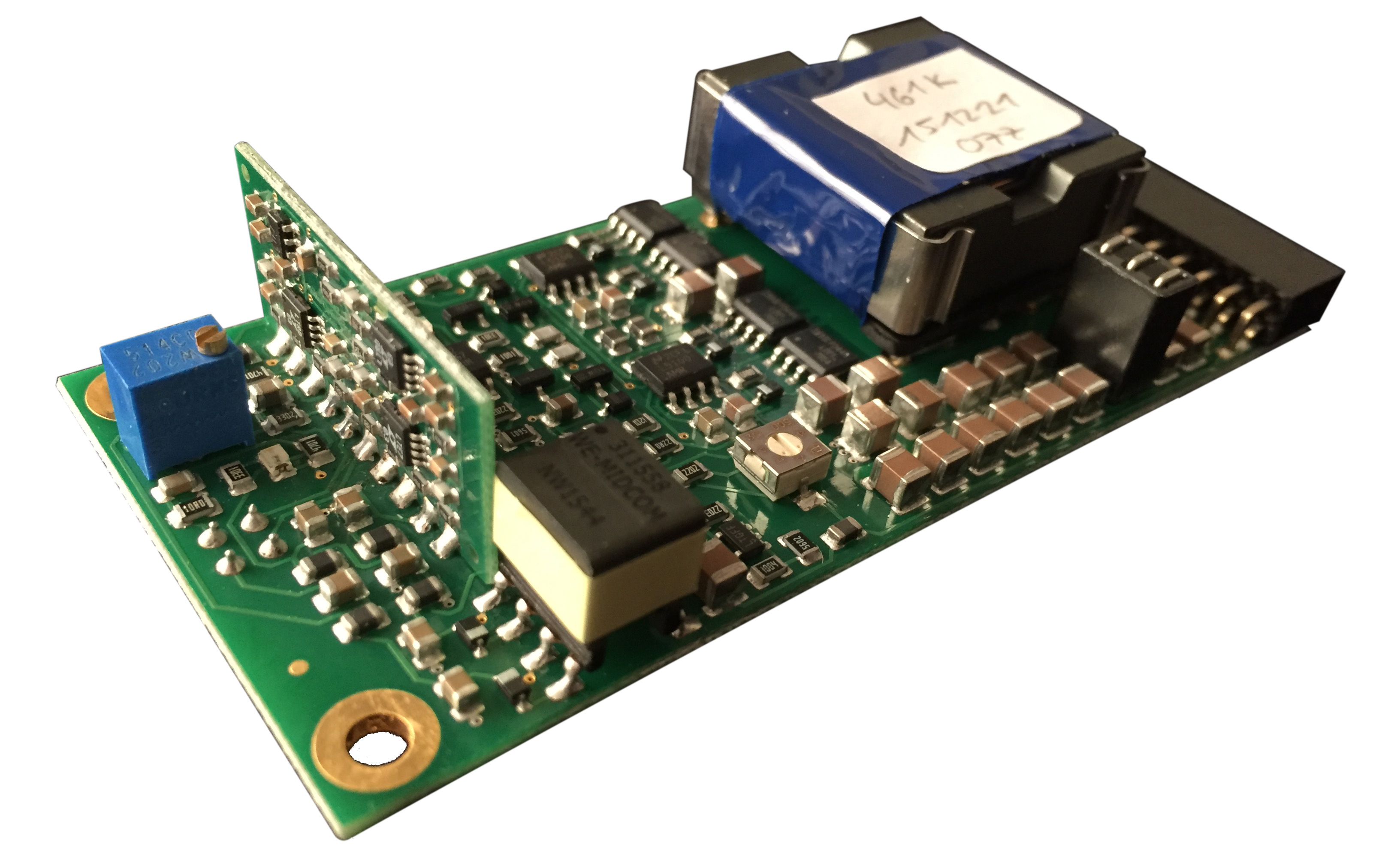
The low internal resistance of the power supply, only 30 mΩ, is achieved by connecting 20 electrolytic capacitors in parallel in the power supply, together providing a capacitance of 66,000 μF. Due to the high charge capacity and because the PWM amplifiers generate virtually no heat losses, the supply voltage hardly drops even during strong bass impulses, so a toroidal transformer with 250 W continuous power is sufficient for both stereo channels to provide clean sine wave output power of 2 x 180 W at 4 Ω:
The real power amplifier is practically as good as in the simulation. Deviating from the simulation, power MOSFETs are used that have an even lower RDSON of 13 mΩ with the same switching speed. The 120 μF at the power switching stage consists of numerous parallel-connected X7R ceramic multi-layer capacitors, effectively blocking high-frequency voltage spikes with maximum efficiency. The PCB layout, created with UltiBoard, is optimized down to the smallest detail, and the entire power electronics are housed on a double-sided board measuring only 40 x 88 mm2. All signal-carrying traces are only a few millimeters long and are placed over solid copper planes with the respective reference potential. The actual Sinus-Cosine Modulator is built with maximum packing density on a module standing vertically to the base board and is powered by a miniature switch-mode power converter with galvanic isolation, whose regulated output voltages are completely smoothed via a 4th-order filter chain with damping ferrite beads and high-capacitance ceramic capacitors. No cooling is required, and the power amplifier module can be operated safely without an EMI-shielding metal housing.
Because SINCOS® power amplifiers produce no audible distortion up to maximum power, even experienced listeners may find it difficult to determine when the driven speaker is overloaded. Unlike conventional amplifiers, which sound audibly "strained" at high volumes, a Sinus-Cosine Modulator can reproduce extreme volume levels effortlessly, which are only perceived as "unpleasant" when the connected speaker is no longer capable of handling them and needs to be replaced. Therefore, each amplifier module has an intelligent overcurrent protection system, set to the specific speaker driver being powered. Before the speaker is overloaded, the amplifier module shuts down (indicated by a red LED) and automatically and quietly restarts after a delay. The volume level just needs to be reduced slightly to prevent further shutdowns.